
CATERPILLAR 123-1379,152-4128,178-7293,CR6590 E345/E349 Track Bottom Roller Assembly / Heavy duty crawler excavator undercarriage parts source manufacturer and supplier/HAN GONG-DPW PARTS

Product Specifications
Comprehensive Technical Specification: CATERPILLAR 123-1379 / 152-4128 / 178-7293 / CR6590 E345/E349 Track Bottom Roller Assembly
1. Executive Product Overview and Functional Definition
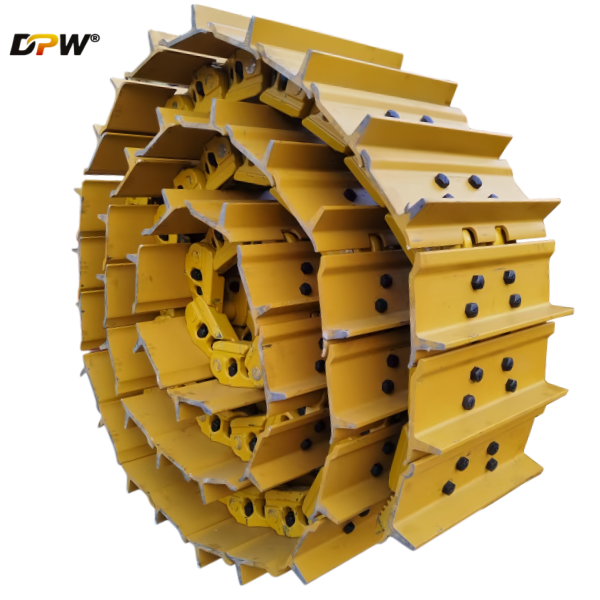
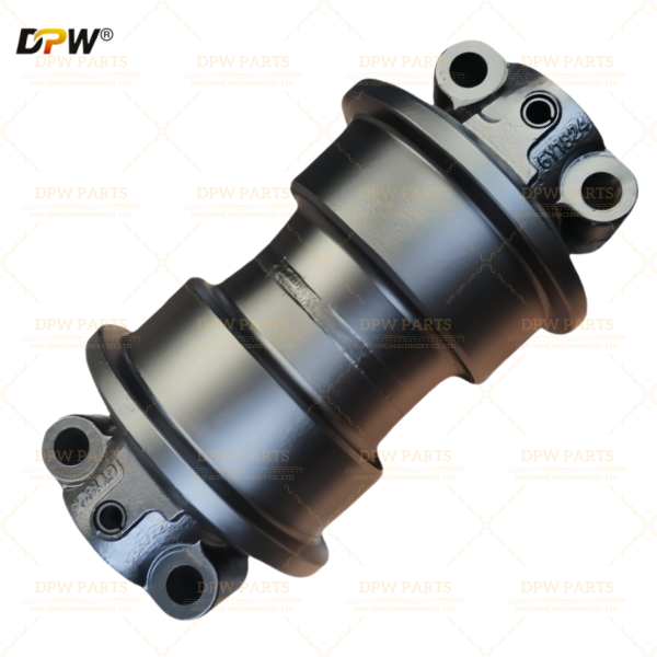
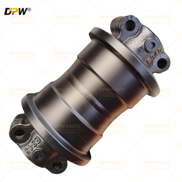
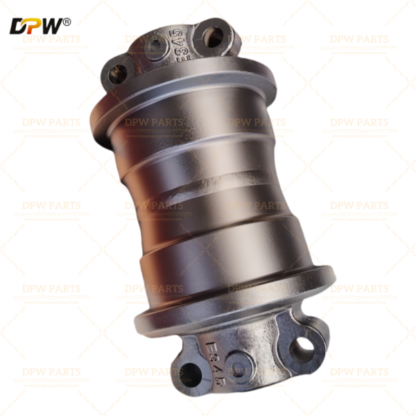
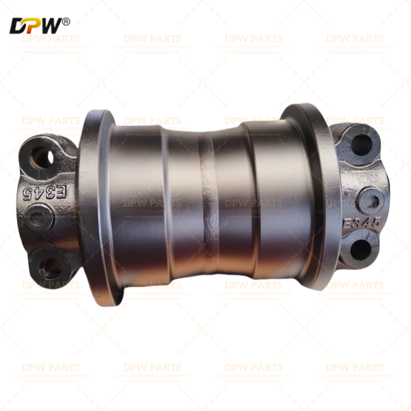
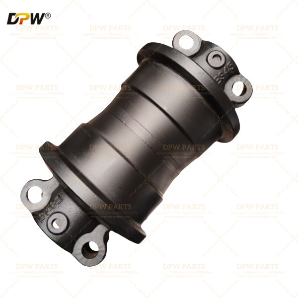
The CATERPILLAR 123-1379 / 152-4128 / 178-7293 / CR6590 Track Bottom Roller Assembly represents a mission-critical load-bearing component within the undercarriage system of Caterpillar E345 and E349 series heavy-duty hydraulic excavators. This assembly, precision-engineered and supplied globally by HAN GONG / DPW PARTS, serves as the primary interface between the machine's weight-bearing structure and the ground-contacting track chain.
As a fundamental element of the crawler undercarriage "four wheels and one track" system, this bottom roller assembly—also referred to as a lower roller or track support roller—is engineered to withstand extreme cyclic loading, abrasive wear, and environmental contamination characteristic of mining, quarrying, heavy construction, and large-scale earthmoving operations . The component's integrity directly influences machine stability, travel performance, track alignment, and overall undercarriage service life.
Manufacturer Profile: HAN GONG Machinery, operating under the DPW PARTS distribution brand, is a technology-driven enterprise established in 2018, headquartered in Nan'an, Quanzhou—China's premier construction machinery component manufacturing hub. With a modern industrial park spanning 20 acres and 10,000 square meters of production facilities, the company specializes in the research, development, and manufacture of undercarriage systems serving over 50 countries worldwide .
2. Engineering Specifications and OEM Part Number Rationalization
2.1 Part Number Cross-Reference and Application Matrix
The product offering encompasses multiple OEM reference numbers corresponding to specific machine configurations, production periods, and component variations:
| OEM Part Number | Machine Application | Component Designation | Engineering Significance |
|---|---|---|---|
| 123-1379 | Caterpillar E345/E349 | Track Bottom Roller Assembly | Standard configuration for medium-duty applications |
| 152-4128 | Caterpillar E345/E349 | Heavy-Duty Bottom Roller | Reinforced design for severe service conditions |
| 178-7293 | Caterpillar E345/E349 | Track Support Roller | Updated specification with enhanced sealing |
| CR6590 | Caterpillar E345/E349 | Commercial Reference Number | Industry-standard cross-reference identifier |
| E345/E349 | Series Designation | Platform Compatibility | 45-50 ton class excavator applications |
Source Note: Manufactured by HAN GONG and distributed through DPW PARTS as a premium aftermarket alternative, this assembly undergoes rigorous quality assurance protocols to meet or exceed original Caterpillar specifications. The manufacturer maintains vertical integration from material sourcing through final assembly, ensuring consistent quality and performance .
2.2 Dimensional and Performance Parameters
The engineering specifications for this assembly are precisely calibrated to match the original equipment interface requirements for Caterpillar E345/E349 series excavators:
Physical Configuration
Roller Type: Sealed and Lubricated (S&L) Track Bottom Roller with dual-flange design for enhanced track guidance
Flange Configuration: Double flange construction providing positive lateral track containment during steering and side-slope operations
Outer Diameter: Precision-machined to match track chain rail dimensions
Mounting Configuration: Bolt-on design with specific bolt pattern matching E345/E349 track frame interfaces
Overall Width: Dimensioned to accommodate specific track guide clearance requirements
Material and Metallurgical Properties
Roller Wheel Material: Forged high-manganese alloy steel (50Mn, 40Mn2, or 60Si2Mn variants) ensuring optimized grain flow for impact resistance and fatigue life
Shaft Material: High-tensile alloy steel (42CrMo) through-hardened for consistent strength and resistance to bending stresses
Bushing Material: Sintered bronze or high-density wear-resistant composite for extended service life under rotational loads
Surface Hardness: 55-63 HRC (Rockwell C Scale) on running surface and flanges
Case Depth: 6-12mm induction-hardened layer ensuring wear resistance throughout service life
Core Toughness: 30-42 HRC maintaining ductility for shock absorption
Shaft Hardness: Optimized for strength while maintaining machinability
3. Technical Component Breakdown and Engineering Analysis
3.1 Roller Wheel and Flange Design
The roller wheel constitutes the primary wear component and load-bearing interface with the track chain. HAN GONG/DPW PARTS employs advanced manufacturing methodologies to ensure structural integrity:
Manufacturing Process: The roller wheel undergoes closed-die forging from vacuum-degassed alloy steel (typically 50Mn or 40MnB series), eliminating internal porosity and ensuring directional grain orientation following the component's stress patterns . This forging process provides superior impact strength and fatigue resistance compared to cast alternatives, which is essential for large excavators operating in mining and quarry environments.
Dual-Flange Configuration: Integrated lateral guides on both sides of the tread provide positive track chain containment, preventing disengagement during side-loading events, counter-rotation maneuvers, and operation on slopes
Flange Geometry: Optimized profile matching track chain link inner contours for uniform load distribution
Reinforced Section Thickness: Additional material at flange roots to withstand high-impact side loads
Running Surface Design:
Tread Profile: Precision-machined contour matching track chain rail configuration
Wear Indicators: Engineered wear limits allowing visual inspection for serviceability assessment
3.2 Shaft and Bearing System Engineering
Shaft Design and Manufacture :
Material Grade: High-carbon chromium alloy steel (42CrMo or equivalent) selected for optimal strength-to-weight ratio
Heat Treatment: Quenched and tempered to achieve through-hardened properties with excellent resistance to bending fatigue
Surface Finish: Precision-ground journals with controlled surface finish (Ra 0.4-0.8μm) minimizing friction and wear
Retention Mechanism: Press-fit and mechanically secured configuration preventing axial movement during operation
Bearing System Configuration :
Bearing Type: Heavy-duty double-row tapered roller bearings or sintered bronze bushing systems, depending on specific design iteration
Load Capacity: Engineered to handle combined radial loads (from machine weight) and axial thrust loads (from steering and side-slope operation)
Clearance Optimization: Precisely controlled internal clearances accommodating thermal expansion while maintaining proper load distribution
Lubrication Distribution: Internal galleries ensuring uniform lubricant distribution to all bearing surfaces
3.3 Advanced Sealing Technology
The service life of the bottom roller assembly is primarily determined by sealing system integrity. HAN GONG/DPW PARTS employs a multi-stage, labyrinth-style sealing architecture :
Primary Seal System:
Radial Lip Seal: Spring-loaded, heavy-duty Nitrile (NBR) or Hythane® compound lip seal creating the primary dynamic barrier
Material Properties: Selected for resistance to abrasion, heat degradation (continuous operation to 120°C), and chemical exposure
Lip Geometry: Optimized contact pressure maintaining seal integrity throughout service life
Secondary Defense Mechanisms :
Labyrinth Seal: Complex multi-channel mechanical seal creating a tortuous path that effectively deflects, traps, and ejects abrasive contaminants including mud, slurry, and fine particulate matter
External Dust Lip: First line of defense excluding coarse contaminants before they reach the primary seal
Grease Barrier: Seal cavity packed with high-temperature, extreme-pressure (EP) lithium complex grease creating positive pressure actively repelling contaminant ingress
Pressure decay testing on every assembled unit verifies sealing system integrity
Accelerated life testing in abrasive slurry conditions validates performance in extreme environments
3.4 Lubrication System Design
Type: High-viscosity, lithium complex EP (Extreme Pressure) grease
Temperature Range: Maintains lubricity from -30°C to +150°C
Additive Package: Enhanced with anti-wear, anti-oxidation, and corrosion inhibitors
Configuration Options:
Sealed-for-Life Design: Pre-filled during manufacture, eliminating field lubrication requirements for standard applications
Maintenance-Friendly Option: Grease fitting (zerk) provided for periodic re-lubrication in severe service conditions and for outer seal barrier maintenance
4. Metallurgical Science and Heat Treatment Protocol
4.1 Material Selection Rationale
The selection of specific alloy steels for bottom roller components reflects optimized engineering for the demanding E345/E349 application :
50Mn / 40Mn2 / 40MnB Series Alloy Steels:
Manganese Content: 1.0-1.5% providing solid solution strengthening and improved hardenability
Boron Microalloying (in 40MnB): Enhances hardenability, allowing consistent through-hardening in larger cross-sections
Grain Refinement: Controlled processing ensures fine austenitic grain structure for optimal mechanical properties
42CrMo Alloy Steel for Shaft Applications:
Chromium Content: 0.9-1.2% improving hardenability and providing moderate corrosion resistance
Molybdenum Content: 0.15-0.25% enhancing temper resistance and high-temperature strength
Carbon Content: 0.38-0.45% balancing strength with ductility and weldability
4.2 Multi-Stage Heat Treatment Process
Stage 1: Quenching and Tempering (Core Treatment):
Austenitizing: Controlled heating to 840-880°C in atmosphere-controlled furnaces ensuring uniform temperature distribution
Quenching: Rapid cooling in specialized polymer or oil quenchants achieving full martensitic transformation
Tempering: Reheating to 500-650°C to achieve desired core hardness (30-42 HRC) while optimizing toughness and ductility
Result: Uniform, tough core structure capable of absorbing massive shock loads without catastrophic cracking
Stage 2: Induction Hardening (Surface Treatment) :
Selective Application: Induction coils precisely target running surfaces and flange contact areas
Heating Rate: Rapid induction heating (seconds) to austenitizing temperature
Quenching: Immediate water or polymer spray quenching creating hard martensitic case
Case Depth: Controlled 6-12mm depth ensuring wear resistance throughout service life
Surface Hardness: 55-63 HRC providing maximum resistance to abrasive wear
Stage 3: Stress Relieving:
Temper Embrittlement Prevention: Controlled cooling through critical temperature ranges
Residual Stress Management: Optimized process parameters minimizing distortion while maintaining beneficial compressive surface stresses
5. Integration with Excavator Undercarriage Systems
5.1 System-Level Function within the E345/E349 Undercarriage
The Track Bottom Roller Assembly performs multiple critical functions within the complete undercarriage architecture :
Load Bearing and Distribution:
Supports a significant portion of the excavator's operational weight (approximately 45-50 tons for E345/E349 class machines)
Transfers loads from the track roller frame through the roller to the track chain and ultimately to the ground
Multiple rollers along the undercarriage distribute weight evenly, minimizing ground pressure and preventing excessive sinkage
The dual flanges securely contain the track chain on both sides, preventing lateral slippage and derailment
Critical during high-stress turning maneuvers where side loads are maximum
Maintains proper track alignment, preventing uneven wear on chain links, bushings, and other undercarriage components
Friction Reduction:
Provides a smooth, hardened rotating surface for the track chain to travel over
Minimizes rolling resistance, contributing to more efficient fuel consumption
Reduces wear across the entire undercarriage system through optimized interface dynamics
5.2 Interaction with Adjacent Components
The bottom roller assembly operates as part of an integrated undercarriage system:
Track Roller Frame: Structural mounting point maintaining roller alignment and providing attachment interface
Track Chain: Continuous engagement with roller running surface, requiring precise dimensional matching for proper load distribution
Adjacent Rollers: Multiple rollers along the undercarriage work in concert to support the machine and guide the track
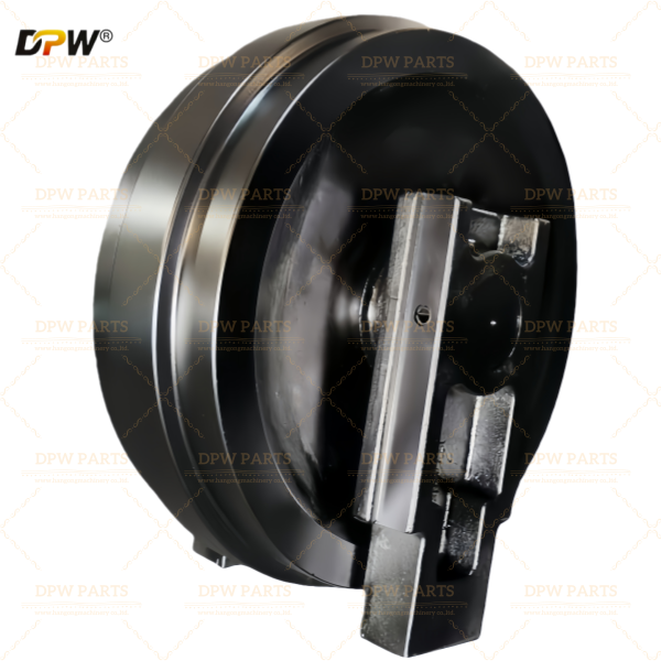
Idler and Sprocket: Work together with rollers to maintain proper track tension and alignment
6. Manufacturing Excellence: HAN GONG / DPW PARTS Capabilities
6.1 Vertically Integrated Production Infrastructure
HAN GONG operates as a specialized undercarriage component manufacturer with complete in-house control of critical processes:
Forging Department:
Multi-ton closed-die forging presses for roller wheel and component production
Precise temperature control ensuring optimal grain flow and material properties
Capability for complex geometries including dual-flange configurations
Heat Treatment Facility:
Controlled atmosphere furnaces for quenching and tempering with precise temperature uniformity
CNC-controlled induction hardening stations for selective surface hardening
Automated handling ensuring consistent process parameters
CNC Machining Center:
Multi-axis machining centers for precision turning, boring, and milling
Capability for complex internal geometries and precise dimensional control
High-throughput production maintaining consistent quality
Assembly and Testing:
Clean-room assembly environment preventing contamination during bearing and seal installation
Automated grease filling ensuring complete cavity fill
Comprehensive testing including rotational torque verification and seal integrity validation
6.2 Quality Assurance and Certification
Each bottom roller assembly undergoes comprehensive inspection protocols:
Incoming Material Inspection:
Spectroscopic analysis verifying alloy composition
Ultrasonic testing for internal soundness of raw material
Hardness verification of incoming stock
In-Process Quality Control:
Dimensional verification at each manufacturing stage
Magnetic Particle Inspection (MPI) of forged blanks detecting subsurface flaws
Hardness testing after each heat treatment stage
Final Inspection:
100% dimensional verification using precision gauges and Coordinate Measuring Machines (CMM)
Rockwell and Brinell hardness testing verifying surface and core properties
Case depth measurement ensuring induction hardening meets specifications
Rotational torque testing confirming smooth, free rotation within specified range
Pressure decay testing validating complete sealing system integrity
Certification and Documentation:
Material test certificates available upon request
Dimensional inspection reports for quality verification
Traceability documentation throughout manufacturing process
7. Selection, Compatibility, and Procurement Considerations
7.1 Compatibility Verification Protocol
When selecting the appropriate bottom roller assembly for Caterpillar E345/E349 applications, the following verification steps are recommended :
Machine Serial Number Confirmation: Provide complete machine serial number to supplier for positive identification
Existing Part Number Verification: Locate and verify part number on existing component
Roller Configuration Inspection: Verify single or double flange configuration matches application requirements
Mounting Pattern Verification: Confirm bolt pattern dimensions match track frame interface
Track Chain Compatibility: Ensure roller profile matches existing track chain configuration
7.2 Procurement Specifications
When ordering the HAN GONG / DPW PARTS bottom roller assembly, specify :
Complete part number reference (123-1379, 152-4128, 178-7293, or CR6590)
Machine model (Caterpillar E345 or E349) and serial number
Quantity required (left and right side positions)
Desired shipping method and packaging requirements
Any special documentation or certification requirements
7.3 Aftermarket Value Proposition
The DPW PARTS offering provides several strategic advantages :
Cost Optimization: Significant savings compared to OEM pricing while maintaining quality standards
Availability: Stock availability for common Caterpillar applications minimizing downtime
Technical Support: Engineering consultation for application-specific requirements
Quality Assurance: Comprehensive quality control meeting or exceeding OEM specifications
Warranty Coverage: Comprehensive warranty against manufacturing defects
Global Logistics: Efficient worldwide shipping via air or sea freight with full export documentation
8. Installation Best Practices and Maintenance Guidelines
8.1 Pre-Installation Inspection
Before installation, conduct the following checks :
Dimensional Verification: Confirm mounting pattern alignment using template or direct measurement
Surface Condition: Inspect mounting surfaces for burrs, damage, or contamination
Rotation Check: Verify roller rotates freely without binding or unusual resistance
Seal Inspection: Examine seal areas for shipping damage or contamination
Thread Condition: Verify all threaded mounting holes are clean and undamaged
8.2 Installation Procedure
Proper installation is critical for service life extension :
Surface Preparation: Clean track frame mounting surface thoroughly, removing all old gasket material, rust, and contamination
Component Positioning: Position roller assembly on mounting surface ensuring proper alignment
Fastener Preparation: Apply appropriate thread locker (typically medium-strength) to mounting bolts
Torque Sequence: Follow OEM-specified torque sequence and values, typically multi-pass tightening to achieve proper clamp load
Final Verification: Rotate assembly to ensure free movement and proper track chain engagement
Track Tension Adjustment: Verify and adjust track tension according to specifications
8.3 Critical Maintenance Parameters
Wear Monitoring Protocol:
Visual Inspection: Regular examination every 250 operating hours for:
Grease leakage around shaft ends indicating seal compromise
Restricted or rough rotation suggesting internal bearing failure
Abnormal flange wear or damage
Running surface wear patterns
Dimensional Measurement: Periodic measurement of flange height and tread diameter against OEM wear limits
Track Tension Verification: Maintain proper track tension to prevent abnormal roller loading
Flange wear exceeding manufacturer specifications
Visible cracking or spalling of running surface
Seal failure evidenced by lubricant leakage
Restricted rotation indicating bearing failure
Simultaneous replacement with worn track chain for matched wear
8.4 Failure Mode Analysis and Prevention
Understanding potential failure mechanisms enables proactive maintenance:
| Failure Mode | Primary Cause | HAN GONG Engineering Solution |
|---|---|---|
| Premature Flange Wear | Abrasive wear, inadequate hardness | Deep induction hardening (55-63 HRC, 6-12mm case depth) |
| Seal Failure & Contamination | Abrasive ingress | Multi-stage labyrinth + double-lip seal system with pressure testing |
| Bearing Spalling | Surface fatigue, contamination | Premium bearing materials, contaminant exclusion through robust sealing |
| Roller Seizure | Bearing failure, contamination | Precision internal tolerances, superior lubrication retention |
| Core Cracking | Impact overload, material fatigue | Forged construction with optimized grain flow, tough tempered core |
| Running Surface Spalling | Surface fatigue, inadequate case depth | Controlled induction hardening with verified case depth |
9. Advanced Engineering Considerations
9.1 Load Distribution Analysis
In a properly engineered undercarriage system, multiple bottom rollers share the machine load simultaneously. The HAN GONG/DPW PARTS roller geometry optimizes this load sharing through :
Precision dimensional control ensuring all rollers contact the track chain uniformly
Optimized running surface profile matching track chain rail configuration
Controlled hardness distribution preventing differential wear patterns
Manufacturing tolerances maintaining consistent engagement across all rollers
9.2 Metallurgical Optimization for Impact Resistance
The selection of forged 50Mn/40MnB alloy steels with controlled heat treatment provides :
Superior Impact Toughness: Forged grain flow orientation aligned with principal stress directions
Optimized Strength-Toughness Balance: Tempered martensitic structure combining high strength with ductility
Fatigue Resistance: Clean steel with minimal inclusions and controlled grain size
Wear Resistance: Hard surface combined with tough core preventing spalling
9.3 Surface Engineering Principles
The induction hardening process creates a metallurgically distinct surface layer with engineered properties :
Martensitic Structure: Hard, wear-resistant surface phase (55-63 HRC)
Compressive Residual Stresses: Improve fatigue resistance and inhibit crack initiation
Gradual Hardness Transition: Prevents spalling at case-core interface
Selective Application: Only wear surfaces hardened, maintaining machinability of mounting features
10. Conclusion and Technical Summary
The CATERPILLAR 123-1379 / 152-4128 / 178-7293 / CR6590 E345/E349 Track Bottom Roller Assembly - Supplied by HAN GONG / DPW PARTS represents a technically advanced, cost-effective solution for maintaining Caterpillar E345 and E349 excavator undercarriage systems in demanding heavy-duty applications.
Through precision engineering, rigorous material selection, advanced heat treatment protocols, and robust sealing system design, this aftermarket component delivers the durability and reliability required for mining, quarry, heavy construction, and large-scale earthmoving operations. The combination of HAN GONG's vertically integrated manufacturing expertise and DPW PARTS' global distribution infrastructure ensures that end users receive components meeting or exceeding original equipment specifications while achieving significant cost optimization.
Key Technical Advantages Summary :
| Parameter | HAN GONG/DPW PARTS Specification | Engineering Benefit |
|---|---|---|
| Construction | Forged alloy steel (50Mn/40Mn2/40MnB) | Superior impact strength and fatigue resistance |
| Surface Hardness | 55-63 HRC (induction hardened) | Maximum wear resistance in abrasive environments |
| Case Depth | 6-12mm controlled depth | Extended wear life through deeper hardened layer |
| Core Toughness | 30-42 HRC (QT condition) | Shock absorption without catastrophic failure |
| Sealing System | Multi-stage labyrinth + double-lip | Superior contaminant exclusion in severe environments |
| Bearing System | Heavy-duty tapered roller or sintered bronze | Reliable performance under combined radial/axial loads |
| Quality Control | 100% inspection, pressure testing | Consistent quality and reliable performance |
Proper selection, installation, and maintenance of these bottom roller assemblies contribute directly to extended undercarriage life, reduced downtime, improved fuel efficiency, and optimized total cost of ownership for heavy equipment operators. For technical consultation, pricing, or additional specifications, contact DPW PARTS directly with your machine details to ensure optimal component selection for your specific application requirements