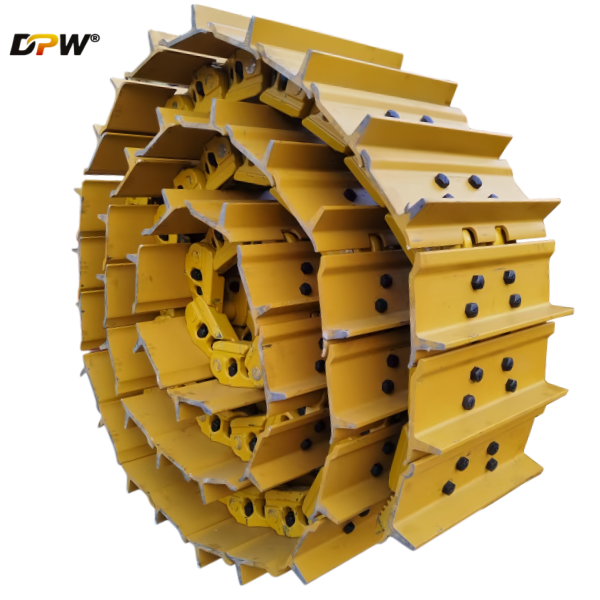


CATERPILLAR CR4589 6T1764 D5H D6M D6N Track Front Idler Wheel Group/DPW PARTS-Heavy industry equipments undercarriage manufacture and supplier
| ||||||||||||||||||||||||||

Product Specifications
Technical Description: Caterpillar D5H Track-Type Tractor Front Idler Group
1.0 Introduction and Functional Overview
The Front Idler Group is a critical sub-assembly within the undercarriage system of the Caterpillar D5H Track-Type Tractor. Its primary functions are:
Track Guidance and Alignment: It serves as the forward guiding point for the track chain, ensuring proper alignment and travel of the track assembly around the main undercarriage components.
Track Tension Adjustment: The idler is mounted on a movable carriage, allowing for precise adjustment of track sag (tension), which is crucial for optimal performance and service life.
Load Bearing and Impact Absorption: It supports the weight of the track frame's front section and absorbs dynamic loads and impacts encountered during operation, such as when the machine traverses uneven terrain or obstacles.
Track Chain Engagement: Its specific contour and diameter are designed to facilitate the smooth meshing of the track chain links as they travel around the idler.
A properly functioning front idler group is essential for minimizing track wear, reducing power loss due to friction, and ensuring stable machine operation.
2.0 Major Components and Their Detailed Specifications
The group is composed of several key components, each with a specific role:
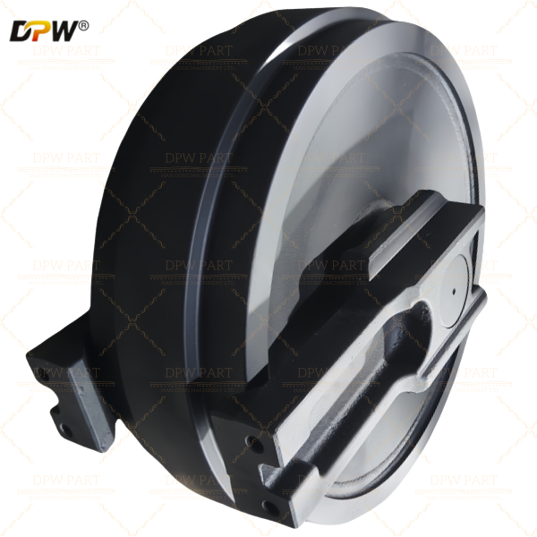
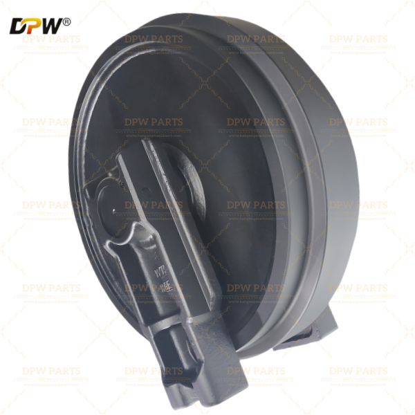
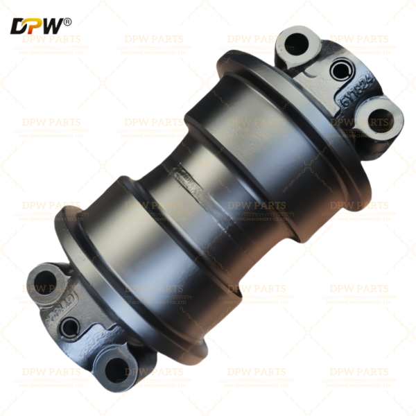
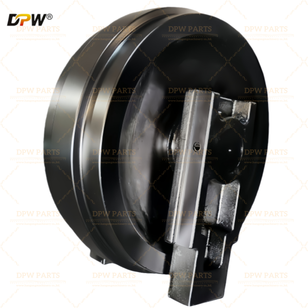
2.1 Front Idler (or Idler Wheel)
Material & Construction: Typically a high-carbon, heat-treated steel casting or forging, designed for high strength and abrasion resistance.
Design: Features a double-flange configuration. The two robust flanges on the outer diameter guide the track chain and prevent lateral derailment.
Running Surface: The surface upon which the track chain bushings (the "pins and bushings") run is hardened to resist wear from continuous contact.
Hub and Bore: The central bore houses the bearings and seals. It is precision-machined to ensure a perfect fit with the idler shaft and bearing assemblies.
2.2 Idler Yoke (or Idler Support Bracket)
Function: This is the structural housing that connects the idler assembly to the main track frame. It houses the idler shaft and the recoil mechanism.
Construction: A heavy-duty, fabricated steel weldment designed to withstand high bending moments and shock loads.
Recoil Cavity: The yoke contains a cylindrical cavity for the recoil spring and related components.
2.3 Recoil Mechanism (Spring and Hydraulic Cylinder Assembly)
This is a defining feature of the D5H undercarriage, providing dynamic tensioning and shock absorption.
Recoil Spring (Coil Spring): A large, high-tensile compression spring located within the idler yoke. It allows the idler to move rearward (recoil) when an obstacle is encountered, momentarily increasing track tension to maintain engagement and absorb energy, thereby protecting the undercarriage from severe shock loads.
Hydraulic Tensioning Cylinder: This component is integral to the adjustment system. It consists of:
Cylinder Body: Fitted into the yoke.
Piston: Acts against the idler shaft.
Grease Fitting (Zerk Fitting): A hydraulic grease pump is connected here to pressurize the cylinder.
Check Valve: A critical component that locks the grease pressure in the cylinder, maintaining the set track tension.
Pressure Relief Valve (Bleeder Valve): A calibrated valve that allows grease to be released safely to reduce tension or that acts as a safety relief if pressure exceeds a safe limit (e.g., due to thermal expansion of the grease).
2.4 Idler Shaft (or Axle Shaft)
Function: The stationary shaft upon which the idler wheel rotates. It is securely anchored to the idler yoke.
Material: A high-strength alloy steel shaft, hardened and ground to a fine finish to serve as the inner raceway for the bearing rollers.
2.5 Bearing and Seal Assembly
Bearing Type: The D5H typically employs a Long-Life Sealed and Lubricated Bearing assembly. This is a cartridge-style unit that includes:
Tapered Roller Bearings: These bearings are pre-adjusted and pre-lubricated at the factory, capable of handling significant radial and axial loads.
Bearing Cartridge: The bearings are housed within a single, sealed unit that is pressed into the idler's hub.
Sealing System: A multi-component sealing system is critical for excluding contaminants (mud, sand, water) and retaining lubricant. It often consists of:
Primary Lip Seals: Usually made of Nitrile (Buna-N) or other durable elastomers.
Exclusionary Seals (or "Scraper Seals"): Often made of polyurethane, these are the first line of defense, physically scraping off mud and debris from the shaft before they reach the primary seals.
2.6 Track Tension Adjuster (Grease Pump)
While not a permanent part of the idler group, the hydraulic grease pump is the essential tool for performing tension adjustments by injecting grease into the tensioning cylinder.
3.0 Operational Principle and Adjustment Procedure
3.1 Dynamic Operation:
During machine operation, the recoil spring allows the idler to move, maintaining constant tension on the track chain as it passes over obstacles. This "give" prevents excessive stress on the track links, bolts, and the final drive.
3.2 Track Tension Adjustment Procedure:
Position the Machine: Place the tractor on level ground with the track un-tensioned (e.g., after moving the machine forward a short distance).
Measure Track Sag: Using a straightedge placed under the track rail, measure the sag at the midpoint between the top of the carrier roller and the top of the front idler. Specification for the D5H is typically 1.0 to 1.5 inches (25-40 mm) of sag.
Adjusting Tension (Increase): Connect a high-pressure grease pump to the tensioner fitting. Pump grease into the cylinder slowly. The piston extends, pushing the idler forward, reducing sag.
Locking the Adjustment: The internal check valve retains the pressure, locking the idler in its new position.
Releasing Tension (Decrease): To reduce tension, slowly open the bleeder valve (usually by loosening it a quarter to a half turn) to allow a small amount of grease to escape. Caution: Do not remove the valve completely, as the high-pressure grease can be ejected with dangerous force.
4.0 Maintenance and Failure Modes
Regular Inspection: Check for excessive flange wear, cracks in the idler or yoke, and oil leaks from the seal area.
Common Failure Modes:
Seal Failure: Leads to contamination ingress and premature bearing failure, often indicated by noisy operation or a stiff-rotating/idler that won't turn.
Flange Wear: Excessive wear can lead to track derailment.
Bearing Failure: Results in looseness, misalignment, and eventual seizure.
Yoke Damage: Cracking or bending from severe impacts can misalign the entire track system.