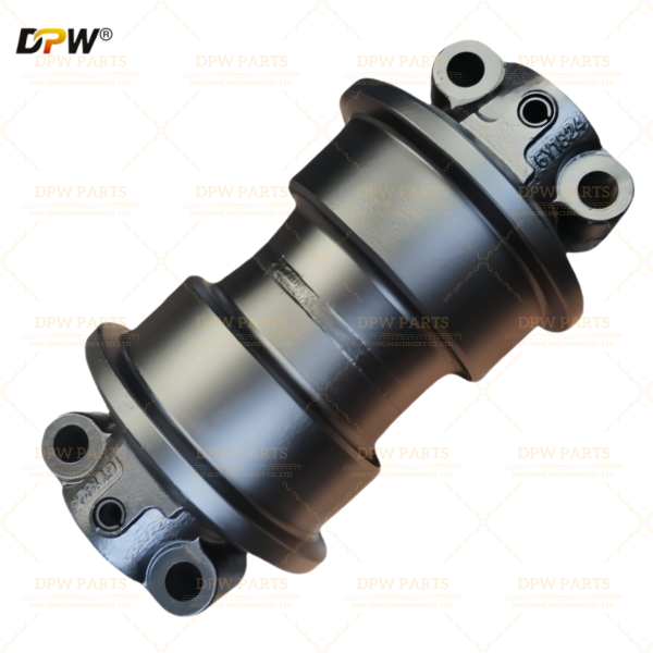

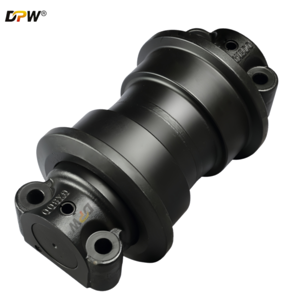
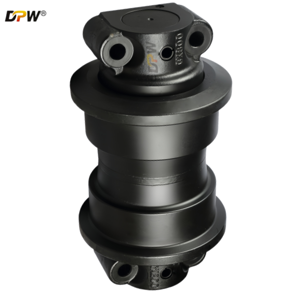
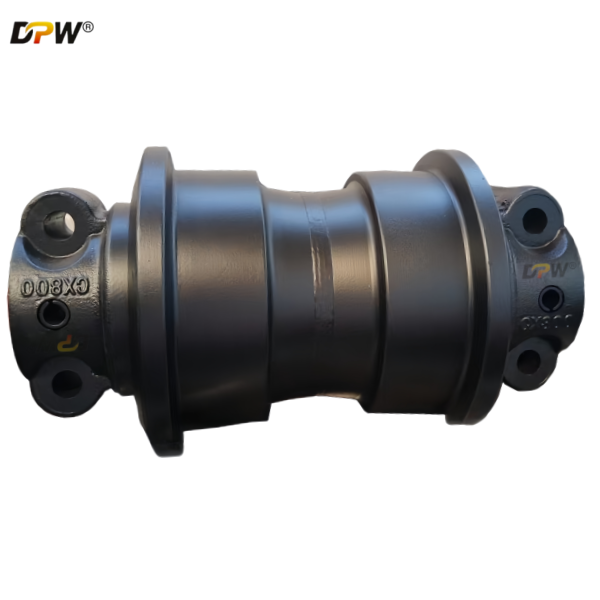
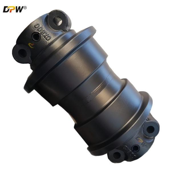
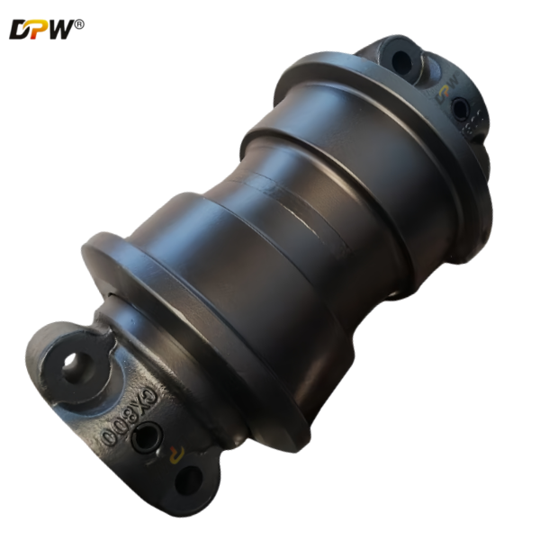
CASE LH1575/6511006/81ND11010 CX800/R984C Track Bottom Roller Group/Case Undercarriage components manufacture in Quanzhou
Product Specifications

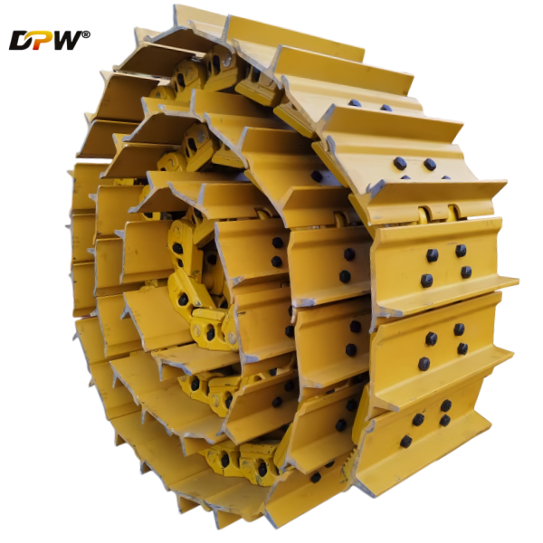
Professional Overview: CASE CX800/CX800B Track Roller Group (Undercarriage)
The Track Roller Group, more commonly referred to as the undercarriage, is one of the most critical and expensive subsystems on a crawler excavator. For the CASE CX800 and its advanced variant, the CX800B—large excavators in the 80-ton class—the undercarriage is engineered for extreme durability, stability, and performance in demanding applications like mining, quarrying, and heavy construction.
1. Primary Function and Importance
The track roller group serves several essential functions:
Support and Distribution: It supports the entire weight of the machine and distributes its immense ground pressure over a larger area to prevent sinking, especially on soft or uneven terrain.
Propulsion: It translates the hydraulic power from the travel motors into linear movement, enabling the machine to travel, position itself, and generate crowd force for digging.
Guidance and Alignment: It guides and keeps the track chain aligned under various load conditions and during steering maneuvers.
Dampening: It absorbs shocks and impacts from uneven ground surfaces, protecting the mainframe and upper structure.
A robust undercarriage is directly linked to machine stability, productivity, and long-term operational costs.
2. Technical Specifications of the CX800B Undercarriage
Based on the technical parameters from the search results, here are the key specifications defining the track roller group's size and capacity:
| Feature | Specification | Implication |
|---|---|---|
| Track Shoe Width | 650 mm | A very wide shoe significantly reduces ground pressure, enhancing stability and enabling operation on softer surfaces. |
| Ground Contact Length | 5,070 mm | A long contact length provides excellent stability, particularly when lifting heavy loads or digging deeply. |
| Track Gauge | 2,820 mm | The distance between the centers of the two tracks. A wider gauge increases side-to-side stability. |
| Total Track Length | 6,360 mm | The overall length of the track assembly. |
| Minimum Ground Clearance | 890 mm | High clearance reduces the risk of the undercarriage contacting obstacles and allows for operation over rough terrain. |
These dimensions paint a picture of a massive, wide, and stable footprint designed for maximum traction and minimal ground disturbance.
3. Key Components of the Track Roller Group
While the exact internal component specifications (like roller diameter) are proprietary to CASE, the group consists of these standard components, built to an extreme duty scale:
Track Frames (Beams): These are the main structural members that house the rollers and connect the undercarriage to the excavator's main frame. They must be incredibly rigid to resist twisting and bending under load.
Track Rollers (Bottom Rollers): These multiple sets of rollers support the machine's weight on the bottom of the track chain. They are typically sealed and lubricated for lifetime operation in high-stress, high-contamination environments.
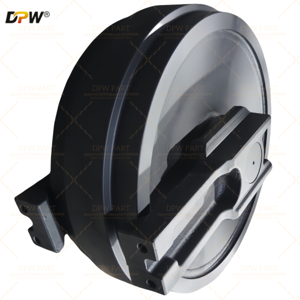
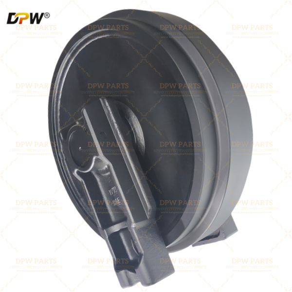
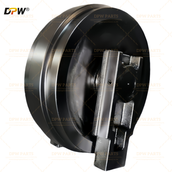
Track Idlers (Front Idlers): Located at the front of the track frame, these wheels guide the track chain and often have a built-in mechanism (like a screw or hydraulic cylinder) for adjusting track tension.
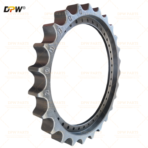
Sprockets (Drive Sprockets): These are meshed with the track chain links and are directly driven by the travel motors. They transmit power to propel the machine. They are made from high-strength, wear-resistant steel.
Track Chains (Link Assemblies): These consist of high-strength alloy steel pins, bushings, and link pairs. The pins and bushings are induction hardened for exceptional wear resistance. The large 650 mm shoes are bolted to these links.
Track Guards (Optional): These help prevent material (like mud, rocks, and debris) from packing inside the undercarriage compartment, which can accelerate wear and put stress on components.
4. Performance and Hydraulic Drive System
The movement of the track roller group is powered by a high-performance hydraulic system:
Travel Motors: The CX800B utilizes variable axial piston motors. This type of motor is highly efficient and can vary its displacement to provide high torque for slow, powerful movements (e.g., climbing) or high speed for easier travel.
Hydraulic Pressure: The travel circuit operates at a high pressure of 34.3 MPa (approx. 343 bar), indicating a robust system capable of generating immense force to move the 80-ton machine.
Travel Speed: The machine has two travel speeds: 2.9 km/h (low) and 4.2 km/h (high).
Ground Pressure: The average ground pressure is 110 kPa, which is remarkably low for a machine of this size, a direct result of the wide, long track footprint.
5. Design and Durability Considerations for the CX800B
Given its target application in mining and heavy excavation, the CX800B's undercarriage is built for extreme durability:
Heavy-Duty Construction: All components are manufactured from special alloy steels and are designed to withstand shock loads from rock faces and constant abrasion.
Sealed and Lubricated Track: The chain (pins and bushings) is likely a sealed and lubricated (SALT) design. This internal lubrication reduces internal wear significantly, extending the life of the most expensive undercarriage components.
Easy Tensioning: Proper track tension is critical for longevity and performance. The CX800B likely features a centralized greasing point or hydraulic system for easy and safe track tension adjustment.
Serviceability: Components like rollers and idlers are typically designed as sealed units that can be replaced individually when worn, without needing to dismantle the entire track frame.
6. Maintenance and Operational Best Practices
Proper maintenance is the largest factor in undercarriage life:
Regular Inspection: Daily checks for track tension, loose or damaged shoes, and leaks from rollers or idlers.
Cleanliness: Keeping the undercarriage free of packed material reduces wear.
Proper Operation: Avoiding high-speed travel on abrasive surfaces, spin-turns, and side-sloping can drastically extend component life.
Tension Management: Maintaining the correct track tension (sag) as specified in the operator's manual is crucial for minimizing wear and power loss.