XCMG 800374986/4600003515 XE370 Track Bottom/Lower Roller Assy/Heavy duty construction machinery undercarriage components manufacturer
| ||||||||||||||||||||||||||

Product Specifications
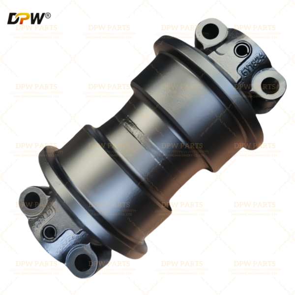
Technical Description: XCMG parts#800374986 XE370 Track Bottom Roller Assembly
1. General Overview & Functional Definition
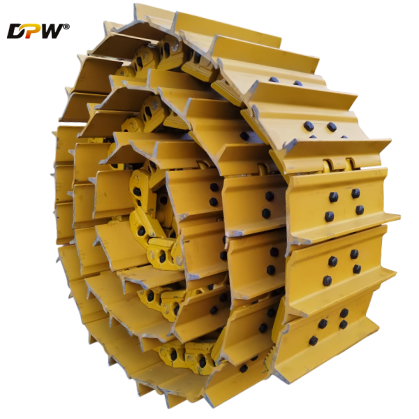
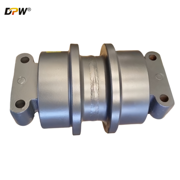
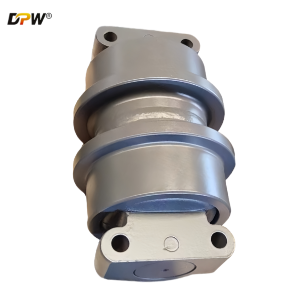
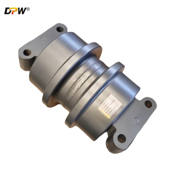
The XCMG XE370 Track Bottom Roller Assembly is a critical, high-stress component within the undercarriage system of the XCMG XE370 hydraulic excavator. As a primary load-bearing element, it is tasked with supporting the machine's substantial operational weight and facilitating its mobility. Its core functions are:

Primary Load-Bearing and Weight Distribution: It directly supports the majority of the machine's static and dynamic weight, transmitting the load from the mainframe through the track chain and distributing it evenly across the track shoes' ground contact area. This ensures stability and minimizes ground pressure.
Track Chain Guidance and Alignment: It guides the bottom (ground-running) section of the track chain, maintaining its precise linear path and preventing lateral drift between the front idler and the drive sprocket. This is essential for stable travel and preventing de-tracking.
Shock and Vibration Absorption: As the first point of contact for ground-induced forces, it absorbs and dampens vertical shock loads and vibrations from traversing over rough terrain, rocks, and debris. This protects the integrity of the entire undercarriage and the mainframe.
Friction Reduction for Efficient Travel: By providing a continuous, sealed, and lubricated rolling surface, it minimizes the sliding friction between the track chain's inner bushing and the roller frame, enabling efficient machine propulsion and reducing power loss and wear.
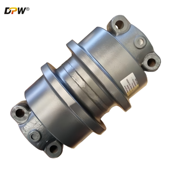
2. Detailed Component Breakdown & Technical Specifications
This assembly is a robust, pre-lubricated, and sealed unit engineered for maximum durability and service life under the extreme loads of a 37-ton class excavator.
2.1. Roller Wheel (or Tread)
Material & Manufacturing: Forged from high-carbon, abrasion-resistant manganese steel such as 55Mn or 60Si2Mn. The forging process guarantees a superior metallurgical grain structure, providing exceptional impact toughness and resistance to fatigue failure compared to casting.
Design Features:
Dual-Flange Design: The roller features two integral, robust flanges. These are precision-machined to provide positive lateral guidance for the track chain's links and bushings, critically preventing lateral slippage (de-tracking) during side-slope operation and steering maneuvers.
Deep Hardened Tread: The outer circumferential running surface is subjected to high-frequency induction hardening. This process creates a deep, hardened case (typically 6-8 mm) with a surface hardness of 58-63 HRC, engineered to withstand the severe abrasive wear caused by the rotating track bushing.
Optimized Profile: The tread and flange are machined with specific radii and contours to ensure smooth engagement with the track bushing and to minimize stress concentration, which can lead to premature cracking.
2.2. Stationary Roller Shaft (Axle Pin)
Function: This is the non-rotating mounting pin that secures the entire roller assembly to the track roller frame. It acts as a structural beam, transferring all operational loads from the roller into the frame.
Material & Specification: Manufactured from high-tensile strength alloy steel, such as 40Cr or 42CrMo, and subjected to a quenching and tempering heat treatment. This provides an optimal combination of high core strength to resist bending and shear forces, and sufficient surface hardness for wear resistance at the mounting points.
2.3. Bearing System
Type: The XE370 typically employs a Long-Life, High-Capacity Needle Roller Bearing or a Double-Row Tapered Roller Bearing configuration. These are selected for their exceptionally high radial load capacity relative to their size.
Function:
Ultra-High Radial Load Support: Specifically engineered to support the extreme weight and dynamic loads of the excavator.
Compact Design: Allows for a larger diameter shaft and more robust roller construction within a confined space, enhancing overall strength.
Pre-lubricated and Sealed: The bearing cavity is packed with high-performance, high-temperature, extreme-pressure (EP) lithium-complex grease during assembly.
2.4. Advanced Multi-Labyrinth Sealing System
Configuration: A critical and robust, multi-barrier sealing system is employed, typically combining a radial lip seal (often Nitrile rubber) with an integrated labyrinth path and sometimes a floating face seal.
Function:
Labyrinth Seal: The first line of defense, designed to physically block large contaminants like rocks, mud, and sand and create a tortuous path that expels debris.
Primary Seal (Lip or Face Seal): This forms the main hydraulic-like barrier, preventing the ingress of fine abrasive particles and moisture into the bearing chamber while retaining the lubricating grease. The seal material is selected for durability and resistance to the operating environment.
2.5. Hub & Outer Housing
The hub is the central rotating component that is pressed into the roller wheel. It contains the precision bore for the bearings and the sealing surfaces.
The outer housing is the structural shell of the roller that directly contacts and supports the track chain bushing. It is designed for maximum wear resistance and structural integrity.
2.6. Lubrication Fitting
Many designs include a grease nipple (zerk fitting) to allow for periodic re-lubrication. This helps to purge any minor contaminants that have bypassed the primary seals and replenishes the grease, extending service life.
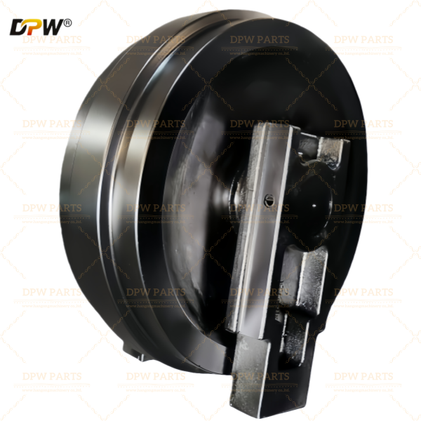
3. Integration within the XE370 Undercarriage System
The Bottom Roller Assembly is a system-critical component:
It is bolted directly onto the Track Roller Frame via the stationary shaft.
It works in concert with the Front Idler, Top Carrier Rollers, and Drive Sprocket to form a continuous track loop.
Multiple rollers (typically 7 or 9) are installed per side to ensure even weight distribution and stable ground contact pressure along the entire track length.
4. Critical Performance & Maintenance Parameters
Wear Limit Adherence: XCMG provides strict maximum wear limits for the roller's outer diameter and flange height. Exceeding these limits allows excessive track sag, leading to accelerated wear on the chain, sprocket, and other rollers, and significantly increases the risk of de-tracking.
Flange Integrity Monitoring: The flanges must be inspected for wear and cracking. Worn or broken flanges can no longer guide the track effectively, leading to lateral track whip and potential failure.
Seal Integrity and Re-lubrication: Regular visual inspection for seal damage (evidenced by grease leakage) is paramount. A seized roller must be replaced immediately to prevent catastrophic damage to the track chain. Adherence to re-lubrication intervals (if applicable) is essential for long service life.
Frame Alignment and Bolt Torque: Proper alignment of the track frame and correct torque on the roller shaft bolts are essential to prevent uneven loading and premature failure.
5. Failure Mode and Effects Analysis (FMEA)
Accelerated Tread Wear: Caused by operation on highly abrasive substrates or chronic improper track tension.
Flange Fracture or Severe Wear: Typically results from aggressive, high-speed turning on hard surfaces or persistent side-loading on slopes.
Bearing Seizure: The ultimate consequence of seal failure, leading to contamination, loss of lubrication, and the roller locking up. A seized roller will rapidly grind down the track bushing, requiring costly replacements.
Shaft Breakage: A rare but severe failure usually caused by an extreme impact or a pre-existing crack propagating from a stress concentrator.