Undercarriage parts of Komatsu 21T3000420 21T3000211 PC2000 Track Bottom/Lower Roller Assy Heavy duty equipments parts manufacturer-DPW Parts
| ||||||||||||||||||||||||||

Product Specifications

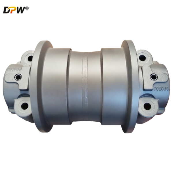
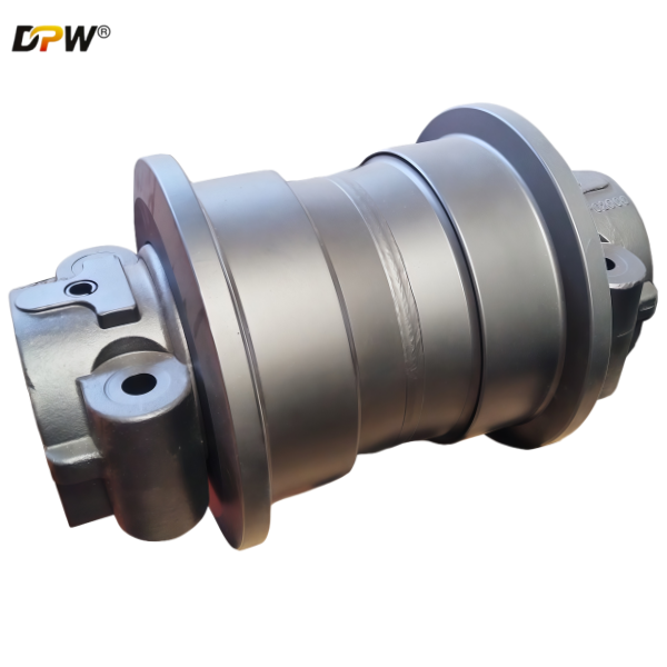
Technical Description: Komatsu PC2000 Track Bottom Roller Assembly (Bottom Track Roller / Track Roller)
1. General Overview & Functional Definition
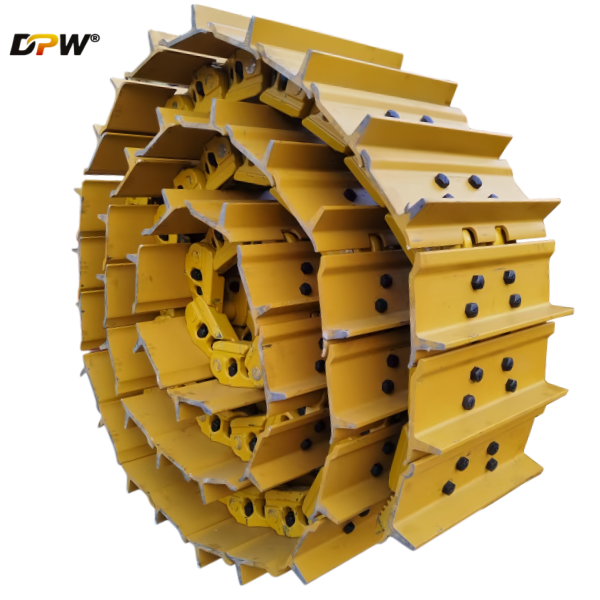
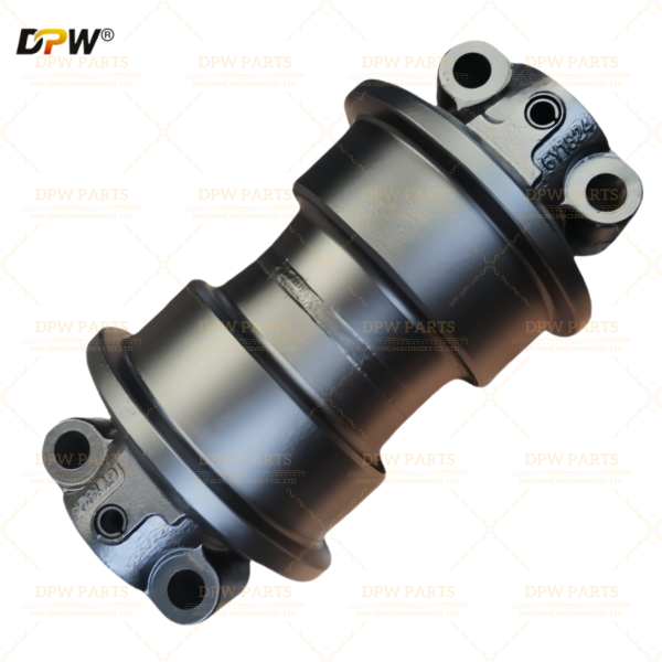
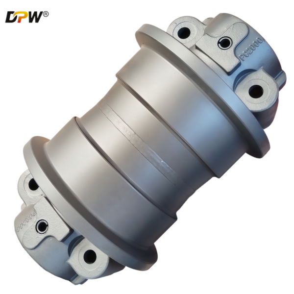
The Komatsu PC2000 Track Bottom Roller Assembly is a fundamental load-bearing component within the undercarriage system of the Komatsu PC2000 hydraulic excavator. Positioned between the track chain and the track roller frame (the "track girders"), its primary functions are:

Primary Load Support: It directly supports the immense weight of the machine, plus its payload, distributing the load evenly through the track chain to the ground. The PC2000, being an ultra-class mining excavator, subjects these rollers to extreme static and dynamic loads.
Track Chain Guidance: The rollers guide the upper section of the track chain's inner link rails, ensuring smooth and continuous travel along the length of the undercarriage. They maintain the correct path of the track, preventing lateral drift and ensuring proper engagement with the sprocket and contact with the front idler.
Ground Contour Adaptation: Multiple bottom rollers installed along the frame allow the track system to conform to uneven ground surfaces, improving stability and traction while distributing ground pressure more effectively.
Friction Reduction: By providing a smooth, rotating surface for the track chain to travel over, they minimize sliding friction, which reduces power loss and wear on the track chain links.
2. Detailed Component Breakdown & Technical Specifications
The assembly is a sealed, self-contained unit designed for maximum durability and service life in the most severe mining environments.
2.1. Roller Wheel (or Roller Body)
Material & Manufacturing: Typically forged from a high-carbon, high-strength alloy steel such as SCM435 (Cr-Mo steel) or an equivalent grade. Forging provides superior metallurgical integrity and fatigue strength compared to casting, which is critical for handling impact loads.
Design Features:
Double-Flange Design: The roller features two integral, robust flanges. These flanges run against the inner guide lugs of the track chain, providing critical lateral guidance and preventing the track from slipping off the roller path.
Hardened Running Surface: The outer circumferential surface, which contacts the track chain's inner link rails, undergoes a deep induction hardening process. This creates a hardened layer of significant depth (e.g., 6-10 mm) with a surface hardness typically between 55-62 HRC. This is essential to resist the severe abrasive wear from the high-pressure contact with the track chain.
Precision Machining: The running surfaces and flanges are machined to precise tolerances to ensure smooth rolling and consistent contact with the track chain.
2.2. Roller Shaft (or Pin)
Function: This is the stationary axle that serves as the mounting point for the entire assembly to the track roller frame. It transmits all operational loads from the roller into the main frame structure.
Material & Specification: Manufactured from high-tensile alloy steel, such as SCM440, and subjected to quenching and tempering heat treatment. This process gives the shaft a high yield strength and exceptional toughness to resist bending and shear forces. The mounting ends and seal contact areas are precision-ground.
2.3. Bearing System
Bearing Type: For an application of this magnitude, Komatsu typically employs a Double-Row Tapered Roller Bearing or large-diameter Spherical Roller Bearings. These bearings are selected for their ultra-high radial load capacity, ability to handle shock loads, and long-term reliability.
Lubrication: The bearing cavity is pre-packed with a high-temperature, extreme-pressure (EP) lithium-complex grease. Many modern designs are "lubed-for-life," meaning they are sealed at the factory and do not require routine greasing, though some may feature a grease fitting for maintenance purposes.
2.4. Multi-Stage Sealing System
Configuration: This is a critical feature for longevity. The PC2000's rollers likely use a sophisticated system such as:
KommTrak Seals (or equivalent): Komatsu's proprietary sealing system, which often combines a radial lip seal with a floating face seal and an external labyrinth seal. This multi-barrier approach is designed to be highly effective in excluding abrasive dust and slurry.
Function: The seals have two primary duties: to prevent the ingress of external contaminants (dust, water, mud) and to retain the lubricating grease within the bearing chamber. The effectiveness of this sealing system is the single most important factor determining the service life of the roller assembly.
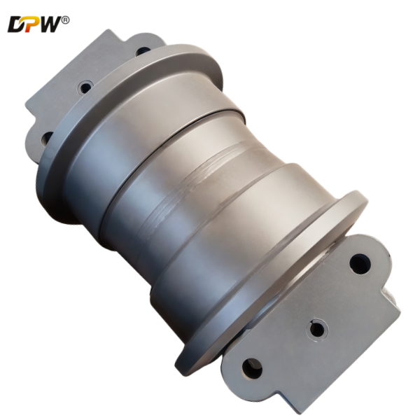
2.5. Hub & Housing
The hub is the central component that rotates around the stationary shaft. It houses the bearings and provides the structural body for the roller wheel.
The assembly is secured to the track roller frame via the roller shaft, which is bolted or pressed into the frame.
3. Integration within the PC2000 Undercarriage System
The Bottom Roller Assembly works in conjunction with other key undercarriage components:
It is positioned below and supports the Track Chain Assembly.
It aligns vertically with the Top Carrier Rollers which support the upper run of the track.
Its condition directly affects the wear on the track chain's inner link rails and itself. A worn roller will accelerate wear on the much more expensive track chain.
4. Critical Performance & Maintenance Parameters
Flange Wear Measurement: The primary wear indicator is the reduction in flange height and width. Komatsu provides strict maximum wear limits. Worn flanges lose their ability to guide the track, increasing the risk of de-tracking and causing uneven, accelerated wear on the track chain.
Roller Diameter Wear: The outer diameter of the roller is also subject to wear. Operating beyond the specified wear limit reduces ground clearance and changes the track's geometry, leading to poor machine stability and increased wear on other undercarriage components.
Seal Integrity: Regular visual inspection for grease leakage (indicating seal failure) or damage to the external seal surfaces is crucial. A failed seal will lead to rapid contamination and bearing failure, necessitating a complete roller rebuild or replacement.
Rotation Check: A roller that fails to rotate freely (seized) will act as a brake, causing severe grinding and accelerated wear on the track link. Regular inspection for free rotation is a standard maintenance procedure.
5. Failure Mode and Effects Analysis (FMEA)
Premature Flange Wear: Caused by excessive side-loading during turning, operating on abrasive rock, or misaligned undercarriage components.
Bearing Seizure: The direct result of seal failure, leading to contamination ingress, loss of lubrication, and eventual lock-up. This can severely damage the roller shaft and hub.
Spalling or Cracking of the Running Surface: Resulting from extreme contact stress, material fatigue over thousands of hours, or hardened material defects.
Shaft Shearing or Bending: A catastrophic failure typically caused by an extreme overload event, such as the machine sliding into a large rock obstruction.
|