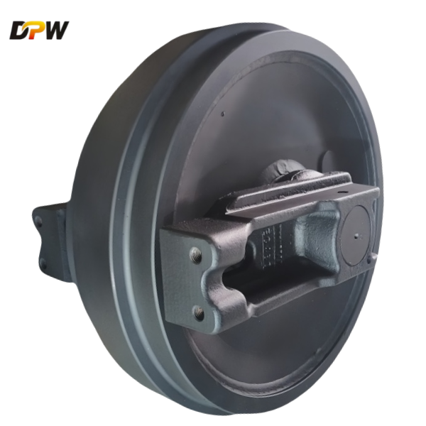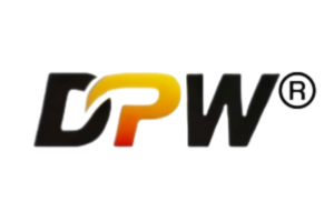
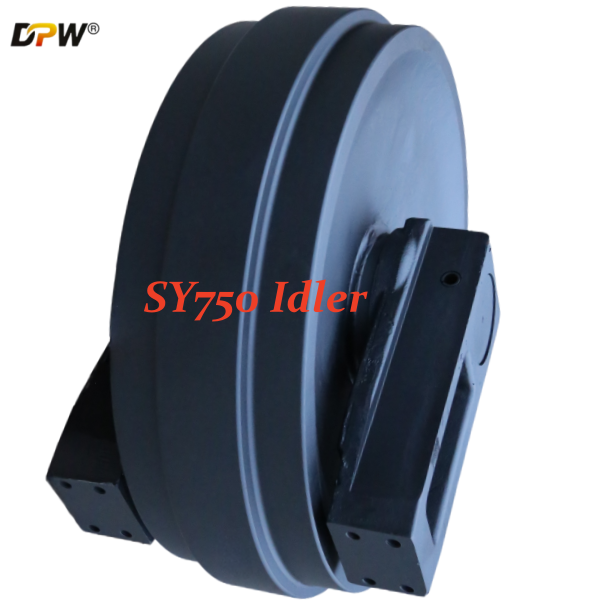

SANY SY700/SY750 Track Front Idler Wheel Group/DPW Prats supply high quality heavy duty crawler excavator undercarriage parts
| ||||||||||||||||||||||||||

Product Specifications

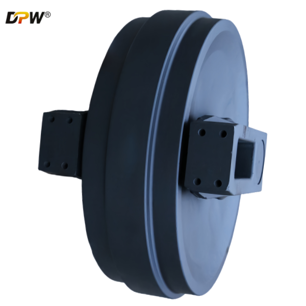
Technical Description: SANY SY750 Track Front Idler Wheel Group
1. General Overview & Functional Definition
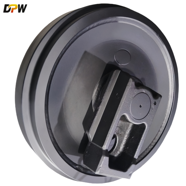
The SANY SY750 Track Front Idler Wheel Group is a pivotal, non-driven sub-assembly within the heavy-duty undercarriage system of the SANY SY750 hydraulic excavator. It functions as the forward guide and primary tensioning mechanism for the track chain. Its core responsibilities are:
Track Guidance and Alignment: It acts as the definitive forward guide point, ensuring the track chain enters and exits the undercarriage structure in a controlled, linear path, maintaining proper alignment with the rollers and sprocket.
Dynamic Track Tensioning: The entire idler group is mounted on a sliding mechanism connected to a hydraulic tensioning cylinder. This allows for precise adjustment of track chain sag, which is critical for optimizing propulsion efficiency, reducing overall undercarriage wear, and preventing catastrophic de-tracking.
Load Support and Impact Initiation: It bears a portion of the machine's dynamic weight and is the first component to absorb and dissipate impact loads from traversing over obstacles, uneven ground, and debris, transmitting these forces into the main track frame.
Facilitation of Track Articulation: The idler's hardened, circular profile provides a smooth, low-friction surface over which the track chain bushings can pivot and articulate, enabling the continuous track loop.
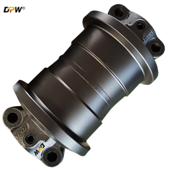
2. Detailed Component Breakdown & Technical Specifications
The "Group" or "Assembly" nomenclature indicates a fully integrated unit, comprising several key components designed to function as a single, replaceable system.
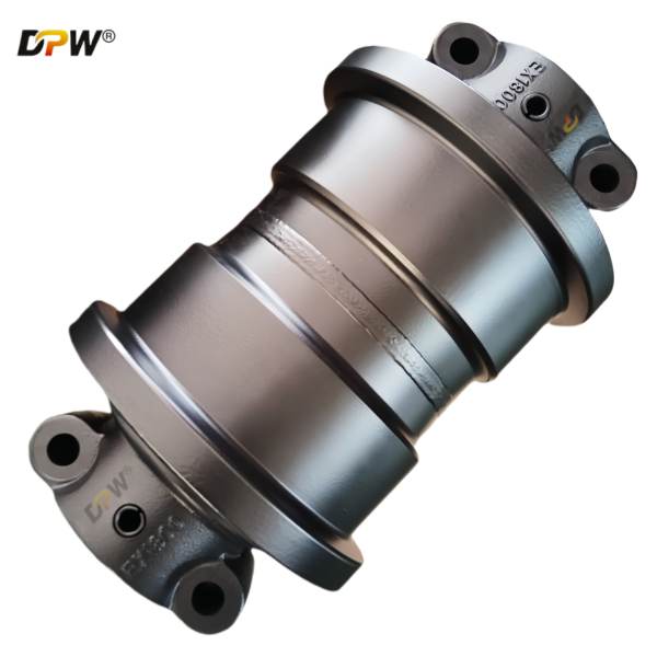
2.1. Idler Wheel (or Idler Rim)
Material & Manufacturing: Fabricated from a high-strength, wear-resistant alloy steel, typically 42CrMo or 50Mn, through a forging process. Forging ensures a superior grain structure, providing exceptional impact toughness and fatigue resistance compared to casting.
Design Features:
Dual-Flange Configuration: The wheel features two integral, robust flanges on its outer diameters. These are precisely machined to provide consistent lateral guidance for the track chain's links and bushings, critically preventing lateral walk-off (de-tracking).
Hardened Running Surface: The outer circumferential surface that interfaces with the track chain bushings undergoes a high-frequency induction hardening process. This creates a deep, hardened layer (typically 5-8 mm) with a surface hardness of 55-62 HRC, ensuring maximum resistance to abrasive wear from the rotating track bushing.
Central Guide Channel: A precisely machined central groove accommodates the track chain's guide lugs (grouser roots), providing an additional layer of lateral stability and centering the track on the idler.
2.2. Idler Shaft (Spindle)
Function: This is the primary structural axle that carries the entire operational load (radial and shock) from the idler wheel to the support arms and ultimately the mainframe.
Material & Specification: Manufactured from high-tensile alloy steel, such as 35CrMo or 42CrMo, and subjected to a quenching and tempering heat treatment process. This gives the shaft a tough, ductile core with high yield strength to resist bending moments and fatigue fracture. The shaft's journal surfaces are precision-ground to a fine finish (e.g., Ra 0.8) for optimal seal performance and bearing fit.
2.3. Bearing and Lubrication System
Bearing Type: The SY750, being a large-scale excavator, typically employs a Double-Row Spherical Roller Bearing or a pair of Tapered Roller Bearings. These are selected for their very high radial load capacity and ability to accommodate slight misalignments.
Lubrication: The bearing chamber is packed with high-temperature, high-pressure lithium-complex grease. A zerk (grease) fitting is standard, allowing for periodic re-lubrication to purge contaminants and extend service life.
2.4. Multi-Stage Sealing System
Configuration: A critical and robust system, often consisting of a multi-labyrinth path combined with radial lip seals and/or floating face seals.
Function:
Labyrinth Seal: The first line of defense, designed to physically block large contaminants and create a tortuous path that abrades and expels mud and dust.
Primary Seal (Radial Lip or Floating Face): This forms the main hydraulic-like barrier, preventing the ingress of fine abrasive particles and moisture into the bearing chamber while retaining the lubricating grease. The seal material is typically Nitrile Rubber (NBR) or Polyurethane (PU) for durability.
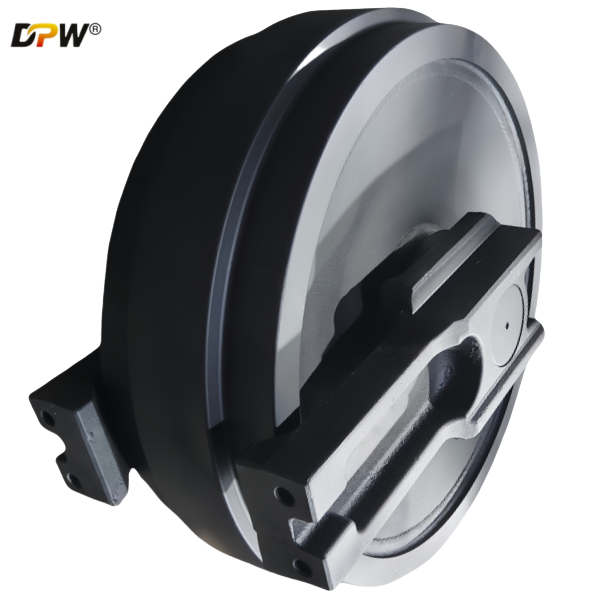
2.5. Hub & Support Housings
The hub is the central forged or fabricated component to which the idler wheel is securely attached. It contains the bore for the bearings and seals.
The support housings (or brackets) connect the idler shaft ends to the track frame's sliding tensioning mechanism. These are designed for high structural integrity to handle shock loads.
2.6. Track Tensioning Interface
The assembly incorporates a forged or machined interface, such as a threaded port or a clevis, that connects directly to the Hydraulic Track Tensioning Cylinder. This allows the mechanic to hydraulically extend the idler to increase track tension or retract it for track removal and maintenance.
3. Integration within the SY750 Undercarriage System
The Front Idler Wheel Group is a key element in a system:
It works in tandem with the Drive Sprocket at the rear to define the track's loop.
It guides the track over the Upper Carrier Rollers and Lower Track Rollers.
Its position directly affects the Ground Contact Length and Track Sag, influencing machine stability, ground pressure distribution, and overall traction.
4. Critical Performance & Maintenance Parameters
Wear Limit Monitoring: The most critical maintenance check is measuring the idler wheel's outer flange height and rim diameter. SANY provides specific maximum wear limits (e.g., flange height reduction by 50%, rim diameter reduction by 15-20mm). Operating beyond these limits drastically increases the risk of de-tracking and accelerates wear on the entire track chain.
Optimal Track Tension: Adherence to SANY's operational manual for track sag is mandatory. A common specification is a sag of 30-50 mm measured at the midpoint between the top of the front idler and the top of the carrier roller. Incorrect tension is a primary cause of premature undercarriage wear.
Seal Integrity & Re-lubrication: Regular visual inspection for grease purging (indicating active sealing) or damage is essential. Periodic re-lubrication per SANY's service intervals is required to maintain seal and bearing health.
5. Failure Mode and Effects Analysis (FMEA)
Accelerated Flange Wear: Caused by chronic operation on severe side slopes, improper track tension, or a misaligned undercarriage.
Bearing Catastrophic Failure: Results from seal failure, leading to contamination ingress and lubricant loss, ultimately causing seizure.
Idler Rim Cracking or Spalling: A consequence of extreme impact loads, material fatigue, or manufacturing defect.
Bent or Sheared Idler Shaft: Typically caused by a severe lateral impact with an immovable object like a rock ledge.