LIUGONG 14C0197 CLG970/CLG975 Track Front Idler Assembly/Heavy duty excavator undercarriage components source factory and manufacture
| ||||||||||||||||||||||||||

Product Specifications

Technical Description: LIUGONG CLG970 Track Front Idler Assembly
1. General Overview & Functional Definition
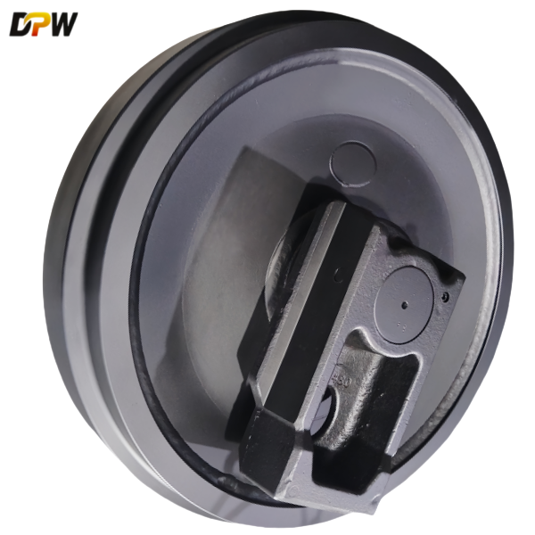
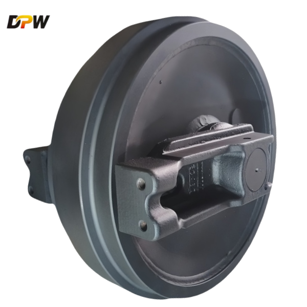
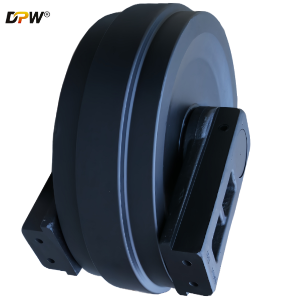
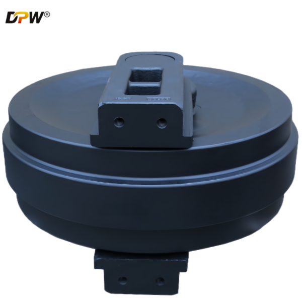
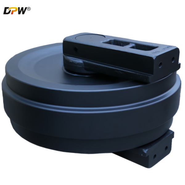
The LIUGONG Part#14C0197 CLG970 Track Front Idler Assembly is a critical, non-driven subsystem within the undercarriage of the LIUGONG CLG970 hydraulic excavator. Its primary functions are multi-faceted:

Track Guidance and Direction Control: It serves as the forwardmost guide for the track chain, ensuring proper alignment and linear travel direction as the track enters and exits the main undercarriage frame.
Track Tensioning: The assembly is not fixed; it is mounted on a movable carriage connected to the track tensioning cylinder. This allows for precise adjustment of track sag, which is crucial for optimal performance, longevity, and preventing de-tracking.
Load Distribution and Impact Absorption: It supports a portion of the machine's weight and absorbs the initial impact loads from obstacles and uneven terrain, transmitting these forces into the main undercarriage frame.
Track Link Articulation Facilitation: As the track links pivot over the idler's curved surface, it ensures smooth articulation and minimizes frictional resistance.
2. Detailed Component Breakdown & Technical Specifications
The assembly is not a monolithic part but a precision-engineered unit comprising several key components:
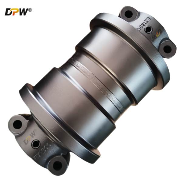
2.1. Idler Wheel (or Idler Rim)
Material & Manufacturing: Typically fabricated from high-carbon, high-strength alloy steel (e.g., SAE 1045/1050) or cast steel (e.g., ZG35SiMn) to withstand extreme shock loads and abrasive wear.
Design Features:
Flanged Design: The idler features two robust, integral flanges on its outer edges. These flanges are critical for containing the track chain and preventing lateral slippage (de-tracking) during side-slope operation or turning.
Hardened Running Surface: The outer circumferential surface, which contacts the track chain bushings, is often induction hardened or flame hardened to a specific depth (e.g., 4-6 mm) and hardness (55-60 HRC). This provides superior resistance to wear from the rotating track bushing.
Machined Groove: A central groove may be machined to accommodate the track chain's guide blocks (or grouser roots), providing additional lateral stability.
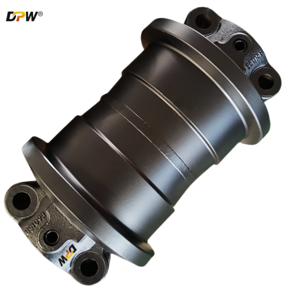
2.2. Idler Shaft (or Spindle)
Function: This is the central load-bearing axle of the assembly. It transmits all operational loads (weight, impact, tension) from the idler wheel to the supporting brackets and the mainframe.
Material & Specification: Manufactured from high-tensile strength alloy steel, such as 42CrMo or similar, and heat-treated (quenched and tempered) to achieve a core toughness that resists bending and fatigue failure. It is precision-ground to a fine surface finish for optimal sealing and bearing contact.
2.3. Bearing System
Type: The CLG970 typically employs a Double-Row Self-Aligning Ball Bearing or a Tapered Roller Bearing setup, housed within a sealed cartridge.
Function:
Load Capacity: Designed to handle significant radial loads from the machine's weight and shock loads.
Misalignment Accommodation: The self-aligning feature compensates for minor misalignments between the idler shaft and the support brackets, preventing premature bearing failure.
Sealed Environment: The bearings are pre-lubricated and housed within a sealed cavity, protecting them from abrasive contaminants like dust, mud, and water, which are prevalent in excavator operating environments.
2.4. Sealing System
Type: A multi-barrier sealing system is employed, commonly a Radial Lip Seal (e.g., Nitrile rubber) combined with a Floating Face Seal.
Function: This robust sealing arrangement is paramount for service life. It prevents the ingress of external contaminants into the bearing chamber and retains the lubricating grease within. The effectiveness of these seals directly dictates the longevity of the entire assembly.
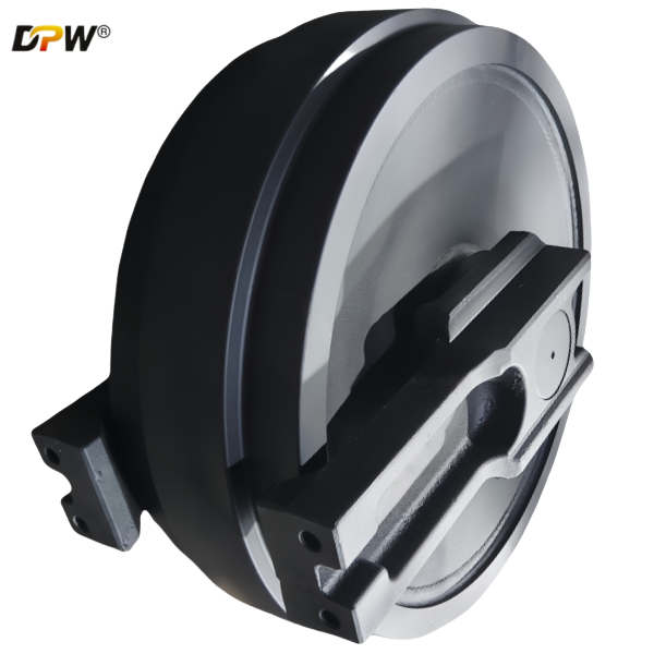
2.5. Hub & Housing
The hub is the central body to which the idler wheel is attached (often via press-fit and welding). It houses the bearings and seals internally.
The housing provides the interface between the idler shaft and the movable track adjustment bracket.
2.6. Track Tensioning Interface
The assembly incorporates a threaded boss or a forged receptacle designed to connect directly to the Track Tensioning Cylinder and Tensioning Rod. This allows the idler to be pushed forward (to increase tension) or retracted (to decrease tension or facilitate track removal).
3. Integration with the CLG970 Undercarriage System
The Front Idler Assembly works in concert with other undercarriage components:
It is the forward counterpart to the Sprocket (the driven component) at the rear.
It guides the track over the Top Carrier Rollers and Bottom Track Rollers.
Its position relative to the sprocket defines the Contact Length of the track on the ground, which affects ground pressure, stability, and flotation.
4. Critical Performance & Maintenance Parameters
Wear Limits: The primary wear point is the outer diameter of the idler wheel. LIUGONG specifies a maximum allowable wear limit (e.g., a reduction in diameter of 10-15mm). Exceeding this limit can lead to rapid wear of the track chain links and bushings, and increase the risk of de-tracking.
Track Tension Adjustment: Proper tension is vital. A rule of thumb is 1-2 inches (25-50 mm) of sag at the midpoint between the top of the front idler and the top of the top carrier roller. Incorrect tension accelerates wear on the idler, rollers, sprocket, and track chain.
Seal Inspection: Regular visual inspection for grease leakage or seal damage is essential. A failed seal will lead to rapid contamination and bearing failure.
Bolt Torque: All fasteners, especially those securing the assembly to the bracket, must be maintained at the manufacturer's specified torque values to prevent structural failure.
5. Failure Mode Analysis
Common failure modes and their causes include:
Premature Flange Wear: Often caused by operating on severe side slopes, misaligned undercarriage, or excessively tight track tension.
Bearing Seizure: Primarily caused by seal failure, leading to contamination and lubricant loss.
Cracked Idler Rim: Resulting from extreme impact loads or material fatigue.
Bent Idler Shaft: Due to severe side impacts with rocks or other solid obstacles.