
Undercarriage System of SANY SY1350 Idler Wheel Assembly/Heavy-duty excavator Crawler Chassis Components Source manufacture and Supplier
| ||||||||||||||||||||||||||

Product Specifications
A Synergy of Strength and Precision
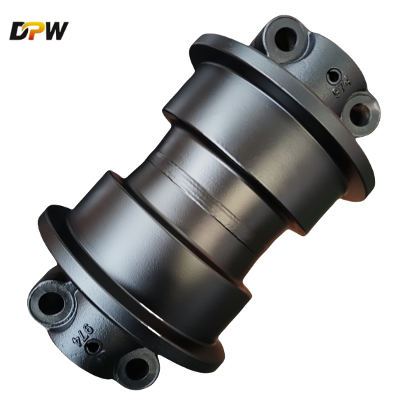
DPW PARTS' SANY SY135C Idler Wheel Assembly is not merely a passive guide wheel; it is an active, integral system for managing track dynamics. Its robust construction, advanced sealing technology, and integrated recoil mechanism work in synergy to ensure maximum undercarriage life, operational stability, and reliability. Understanding its components and function is key to effective maintenance and minimizing the total cost of ownership for the SY1350 heavy-duty excavator.

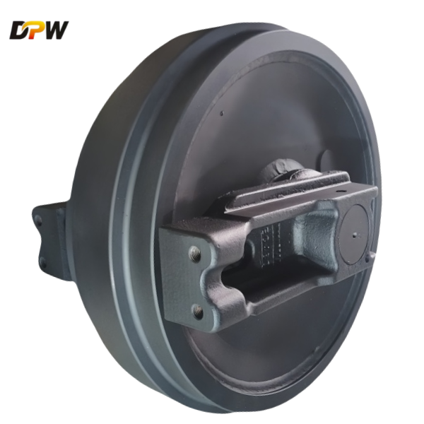
Introduction: The Pivotal Role of the Front Idler
The Front Idler Wheel Assembly is a fundamental and critically engineered component within the undercarriage system of the SANY SY135C Hydraulic Excavator. Positioned at the forward apex of the track frame, it functions as the primary guide and tensioning mechanism for the entire track chain. Its performance directly influences track stability, alignment, service life, and overall machine efficiency. This assembly is engineered to withstand immense static and dynamic loads while operating in the most demanding environments, from abrasive quarries to wet, muddy construction sites.
1.0 Primary Functions and Operational Objectives
The Front Idler Assembly fulfills several key mechanical functions:
Track Guidance and Alignment: It provides the definitive forward point for the track chain's travel, ensuring precise alignment and preventing lateral derailment during operation, especially when turning or traversing slopes.
Track Tension Adjustment: The idler is mounted on a movable carriage. By adjusting its position fore and aft, the operator sets the correct track sag, which is crucial for minimizing power loss, reducing wear on pins and bushings, and preventing track slap and derailment.
Load Support and Impact Absorption: The assembly supports the weight of the track frame's front section and absorbs significant shock loads generated when the track makes contact with obstacles.
Facilitation of Track Chain Movement: Its contoured design ensures smooth engagement and disengagement of the track chain links, promoting efficient power transmission from the sprocket.
2.0 Detailed Component Analysis
The assembly is a sophisticated integration of several key sub-components, each crafted for durability and specific function.
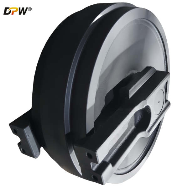
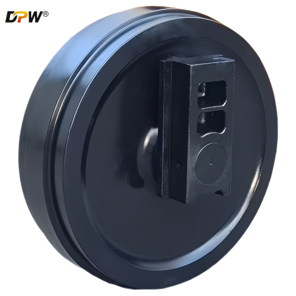
2.1 Idler Wheel (or Idler Rim)
Material Science: Fabricated from high-carbon, low-alloy steel (e.g., SAE 1045 or equivalent) via precision casting or forging. This is followed by a controlled heat-treatment process (quenching and tempering) to achieve a uniform, high-tensile core strength and superior impact resistance.
Geometric Design: Features a robust double-flange configuration. The flanges are integrally cast and machined to precise tolerances to guide the track chain links effectively.
Running Surface: The outer diameter (O.D.) that contacts the track chain bushings undergoes induction hardening. This process creates a deep, exceptionally hard (typically 55-60 HRC) wear-resistant surface, while the core remains tough to absorb impacts. The surface is finely ground to a smooth finish to minimize friction with the track bushing.
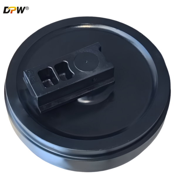
2.2 Idler Yoke (Support Bracket)
Function: This is the structural backbone of the assembly. It securely houses the idler shaft and the recoil mechanism, transmitting all operational loads back to the main track frame.
Construction: A high-strength steel weldment, designed with reinforced ribs and gussets to resist bending and torsional stresses. It is shot-blasted and primed with anti-corrosion coatings to enhance longevity.
2.3 Recoil and Tensioning System
A hallmark of a modern excavator like the SY135C, this system provides dynamic track tension.
Recoil Mechanism: Consists of a large, high-grade compression spring housed within the idler yoke. This allows the idler to move rearward when encountering an immovable object, absorbing the shock load and protecting the undercarriage components from catastrophic failure.
Hydraulic Tensioning Cylinder:
Cylinder Body: A precision-machined bore within the yoke or a separate cartridge.
Piston: Acts directly on the idler shaft.
Grease Fitting (Zerk Fitting): The point for connecting a high-pressure grease pump to adjust tension.
Check Valve: Holds hydraulic pressure within the cylinder, maintaining the set track tension.
Pressure Relief Valve: A safety mechanism that bleeds off excess pressure caused by thermal expansion of the grease or extreme impacts, preventing damage to the cylinder and seals.
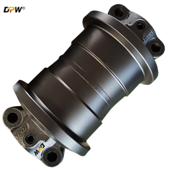
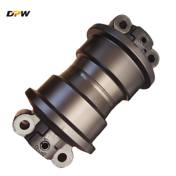
2.4 Bearing and Sealing System (The Heart of Longevity)
SANY employs a advanced, maintenance-free sealed bearing system for extended service life.
Bearing Type: A Pre-lubricated, Double-Row Tapered Roller Bearing Cartridge is standard. This cartridge is pre-adjusted and packed with high-temperature, extreme-pressure (EP) lithium-complex grease at the factory.
Integrated Sealing System: A multi-stage, labyrinth-style seal is employed, often comprising:
Primary Lip Seals: Nitrile rubber seals that provide the main barrier against contaminant ingress and grease egress.
Labyrinth Seal: A complex, tortuous path between the idler and the shaft flange that traps contaminants. This cavity is often packed with grease during assembly to create an additional barrier.
Excluder Lips: Made from durable polyurethane, these lips actively scrape off mud and large debris before they reach the primary seals.
2.5 Idler Shaft (Axle)
Specification: A hardened and ground alloy steel shaft that provides a fixed, precision raceway for the bearing's inner ring. It is securely fastened to the idler yoke via bolts or press-fit and locking mechanisms.
3.0 Key Design Features for Enhanced Performance
Optimized Flange Geometry: The flange profile is designed to guide the track link without creating excessive stress points, reducing flange wear and track link wear.
Forged vs. Cast Construction: Depending on the manufacturing spec, the idler wheel may be forged for maximum strength in severe-duty applications or high-quality cast for optimal cost-effectiveness in standard duties.
Corrosion Protection: A full-dip phosphate or electrocoat priming process is applied to all components before painting to resist rust and corrosion.
4.0 Maintenance, Inspection, and Replacement Indicators
Regular Inspection: Check for flange wear (measuring height reduction), O.D. wear (using calipers), and cracks. Inspect for grease leaks from the seal area, indicating seal failure.
Track Tension Adjustment: Always refer to the SANY SY135C operator's manual for the correct sag measurement (typically 20-40mm). Adjust tension via the grease fitting and relief valve as described in the previous section.
End-of-Life Indicators: The assembly should be replaced when flange wear exceeds 50% of original height, significant O.D. wear is present, or the roller fails to turn smoothly (indicating bearing failure).